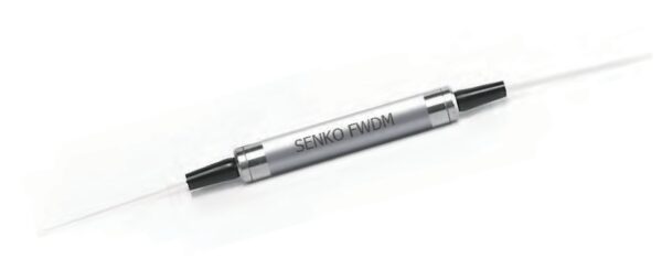
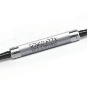
Filter Based FWDM 1310/1550nm
SENKO’s Wavelength Division Multiplexer (WDM) is based on thin-film filter technology, and has two types of isolation which are standard isolation and high isolation. This component us used to combine or separate 1310 and 1550nm band signals. This product is ideal for high-power Optical Amplification Systems and WDM Network applications.
- RoHS Compliant
- Low Insertion Loss
- High Channel Isolation
- Highly Stable and Reliable
- Wide Operation Wavelength Range
| PARAMETERS¹² | VALUE | |
| Pass Channel Wavelength Range (nm), λP | 1530~1600 | |
| Reflection Channel Wavelength Range (nm), λR | 1270~1350 | |
| Insertion Loss (dB) | Com-Pass | ≤0.6 |
| Com-Reflection | ≤0.5 | |
| Standard Isolation (dB) | Com-Pass @λR | ≥30 |
| Com-Reflection @λP | ≥12 | |
| Return Loss (dB) | ≥50 | |
| Directivity (dB) | ≥50 | |
| Polarization Dependant Loss (dB) | ≤0.1 | |
| Pass band Ripple (dB) | ≤0.3 | |
| Fiber Type | SMF-28e, 250µm bare fiber | |
| Package Dimension (mm) | 5.3mm(Ø) x 35(L) for bare fiber | |
| 5.5mm(Ø) x 40(L) for 900µm Loose tube | ||
| Operating Temperature (°C) | 0~+70 | |
| Storage Temperature (°C) | -40~+85 | |
Notes:
1. The tested performances do not include connectors.
2. For a device with connectors, IL will be specified 0.3 dB higher and RL will be 5dB Lower.
3. Specifications may change without notice.
Bi-directional WDM Systems
Cable TV (CATV)
Metro Networks
FTTx


WDM is an acronym for Wavelength Division Multiplexer. The main purpose of the WDM is to increase bandwidth capabilities on a single optical fiber. Signals are sent using different wavelengths across one fiber channel until they are split into their respective lanes. The splitting is called demultiplexing. In reverse, the WDM can combine or multiplex the different wavelengths onto one fiber. This greatly increases the amount of information that can be sent over a single fiber.
CWDM is an acronym for Course Wavelength Division Multiplexer. CWDM is a type of WDM technology, however, the channel spacing is controlled to a recommended spacing called the ITU CWDM grid. In this grid, the channel spacing is 20nm with a channel passband of +/-6.5nm in the center wavelength. According to the ITU grid, the wavelength range is 1270nm to 1610nm where there are 18 individual channels separated by 20nm spacing.
DWDM is an acronym for Dense Wavelength Division Multiplexer. Similar to CWDM’s, a DWDM allows the multiplexing and demultiplexing of more than one wavelength that can be transmitted over one fiber. The difference here, is that the spacing is more dense. This means that the spacing is spaced at 0.8nm/0.4nm for DWDM’s. The wavelength used are from 1525nm to 1625nm which are known as the C Band and L Band wavelength ranges. DWDM’s allow for more channels due to the tight channel spacing.
A regular splitter has no wavelength dependency. This means that if 1310nm or 1550nm get sent into a splitter, both wavelengths are split into the ratio of the splitter. For a WDM, the device will actually block the light from with the wrong wavelength entering the channel and only pass the wavelength that it’s designed to allow through.
