1xN/ 2xN/ 4xN Series
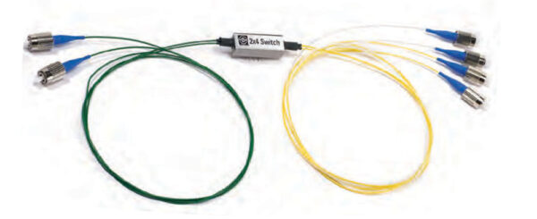
SENKO’s Optical Switch 1xN/2xN/4xN series are based on opto-mechanical technology with high reliable quality. These switches are designed for optical multiplexers, cross-connect and network switching for fault/protection applications.
- Compact Size
- RoHS Compliant
- Low Insertion Loss
- Telcordia GR-1221 and GR-1073
| PARAMETERS¹² | VALUES | ||
| Types | 1×1 / 1×2 /2×4(Dual 1×2)/4×8(Quad 1×2)/2×2 bypass /4×4 bypass | ||
| Wavelength (nm) | 1260~1360 | ||
| Switch type | 1×1 / 1×2 /2×4(Dual 1×2) | 4×8 (Quad 1×2) | 2×2 bypass/ 4×4 bypass |
| Insertion Loss Maximum (dB) | 1.0 | 1.0 | 2.0 |
| Wavelength Dependent Loss (dB) | ≤0.3 | ||
| Polarization Dependant Loss (dB) | ≤0.1 | ||
| Repeatability (dB) | ±0.1 | ||
| Cross Talk (dB) | ≥60 | ||
| Return Loss (dB) | ≥55 | ||
| Switching Time (ms) | ≤3.5 | ≤3.5 | ≤3.5 (2×2)/ ≤5.0 (4×4) |
| Maximum Input Power (mW) | 500 | ||
| Durability (Cycles) | 3×10 | ||
| Operating Voltage Range (V) | 4.5~5.5 | ||
| Power Consumption (mW) | Latching:200±10% / Non-Latching:140±10% | ||
| Dimension (H x W x L) (mm) | 7.6x11x22.6 | ||
| Weight (g) | 10 | ||
| Fiber Type | SMF-28e 250µm fiber or 0.9mm loose tube | ||
| Operating temperature (°C) | -5~+70 | ||
Notes:
1. The specification shows for SM type only but MM type(850/1300nm) is available.
2. The parameters are not including connector performance.
Optical Network Protection and Storage
Network Switching
Reconfigurable Add/Drop Multiplexers
Instrumentation for Test and Measurement


A fiber optic switch is a critical piece of hardware to fiber optic network infrastructure. The main function is to switch the optical path to separate channels in a controlled manner. This can be done remotely via a control device.
If you need to control the path of your optical signal, you may want to look into an optical switch. The Fiber Optic Switch enables many configurations and it’s possible to control traffic coming in or leaving a network. Unlike a splitter, the optical path can be blocked or unblocked on certain channels via remote control.
There are many different configurations that can be applied to custom applications. Feel free to contact us and we will help determine what the best path is for you.
